Change the rotation center of a tile?

Hi,

This probably is not new but I am finding it difficult to readily locate the answer (and am too dumb to discover it myself). Below is the premise and the problem I am trying to solve.

All colored lines are just moments in time of the black one and are 3 inches in length. They rotate from the center. However, I would like for them to rotate from the top-left instead. Which means below are the X and Y coordinates of the line and the adjustment I would need to do to bring the line back to the starting point (so it appears it is rotating from one end instead of the center).

Looking at this - I can see that the formula would be non-linear in nature to carry out the adjustments and would need to use the angle as a variable as well as the length of the line as another variable - however, I am not sure what that formula would look like.

Can anyone please help? I can see that you can draw a circle around it - so is pi a part of the formula?

If we are talking about sprite objects and not tile map object then you simply move center point of sprite object to its origin point which is in upper left
So it would rotate as you want

So would it require any adjustment?

No, that would be easy. I am specifically asking for tile because I am doing an offset transformation on the tiles to make it look like repeating arrows are moving and also they are not scaling but rather duplicating as the line stretches.

Then i am unable to assist you cause i do not even understand it
And if you are talking about tiled object or tile map
I think there will be problems rotating them
At least that is what i remember where i can be wrong

Anyway GL

If you’re talking about rotating the tiled sprite from say the corner then the easiest way is by using the sticker behavior and a pivot object.

Add the sticker behavior to the tiled sprite
Add an object that works as the pivot point
Stick the tiled object to the pivot object
You then change the angle of the pivot object and the tiled sprite will follow it.

I tested it with a slider. The tiled sprite will rotate around the pivot object.

If you’re talking about something more complex then I need a simplier explanation.

This is a longer solution that uses put an object around a position instead of a 2nd object. It depends on the origin object position and the angle and distance from the top center and corner. It can probably be simplified.

Tile sprite variables

I added 180 to the initial angle because I measured the angle backwards. It probably should be from the corner to the center instead of the center to the corner.

@Keith_1357, you sir, are a gentleman and a scholar. Thank you so much. I think I am understanding your second solution (but haven’t tested it yet, just got back from a commitment). I would prefer to not install any extensions - so would try your second method first before conceding to sticker extension.

Please see https://youtu.be/IeahVaz-NGQ?t=30. I am basically trying to replicate the trail effect of duelyst. So when I select and object (left click held down) - it spawns a tile with continuous offset - 1 (to simulate the arrow going forward) in the tile.

Next I want the trail to shrink and expand based on cursor position so I am using DistanceBetweenPoints (which only expands the width of the tile).

Finally I want the angle to follow the mouse, which I am using AngleBetweenPoints. This was posing the issue where the origin point of the cursor would leave the object from where the drag (mouse left click held down) started because the rotation would occur from the center.

I am going to try your methodology tomorrow and see if it solves that problem :).

Here is a much more complicated method but I think it’s much closer. It’s based on another project. A spline method might be better. This is just 1 idea.

Here’s my project. Click the green [Code] and [download zip]
https://github.com/doug13579/gdevelop-add-arrow-targets

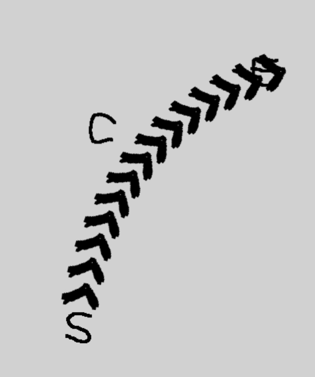
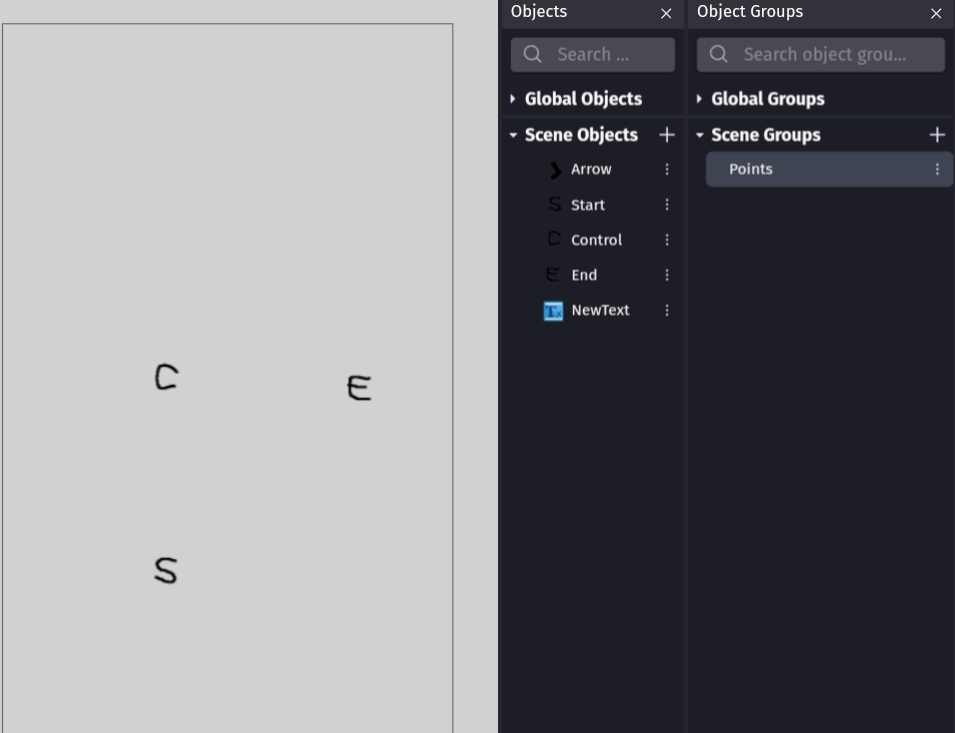
Try it. The S,C and E are draggable.
https://gd.games/keith_13579/arrow-target

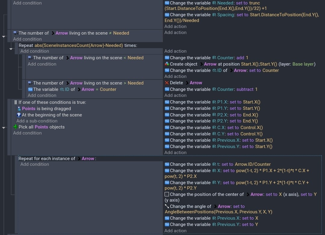
It uses a formula that ChatGPT helped me with that places objects on a quadratic curve. It uses a start, an end and a control object. These objects have the drag behavior for testing. If the control object is in the center, the curve will bend left or right naturally. Although a formula for c might be better. It uses an ID variable on the arrow object to calcute the time (t) The number needs to be between 0 and 1 so it gets divided by the number of objects. The ID will place each arrow along the curve at different times.

It adds and deletes objects based on how many are needed using the distance and space between the objects. If it’s just a matter of clicking a target then the method to delete objects might not be needed. You might be able to just calculate the needed objects once and then delete all the objects when not needed.

Animating the arrows would be trickier. You could add an offset to the time (t) so each arrow would be placed slightly further along the curve. If the offset looped from 0 to the spacing amount, then it should look like objects are being added and deleted. I’m not positive about that though. I think it’s best to get the basic design working first.

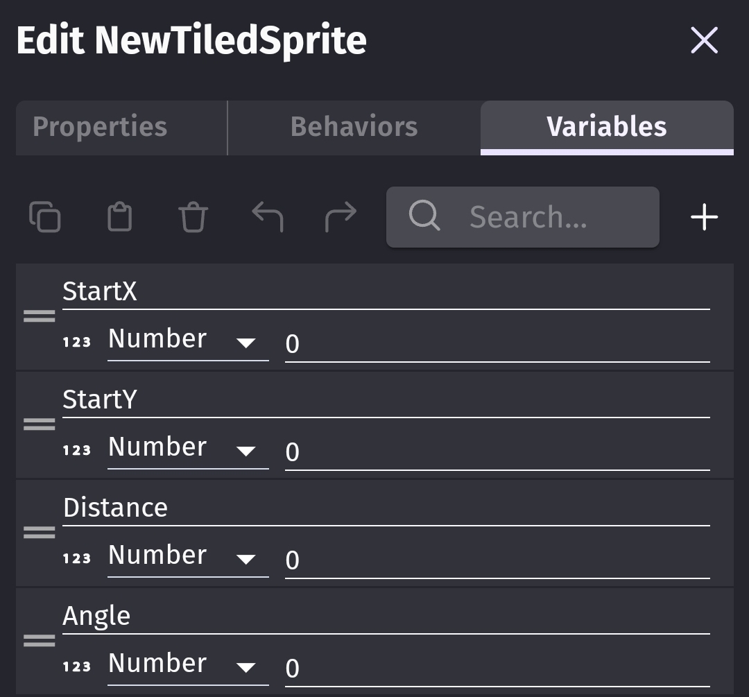
I might have mentioned this but the arrow object has an ID object variable. I don’t believe any of the other objects have any variables.

All objects have their origin and center points in the center. I’m not positive if it’s still necessary but it’s best to be safe. Important, the position action is position based on center. So, the origin point might not matter.

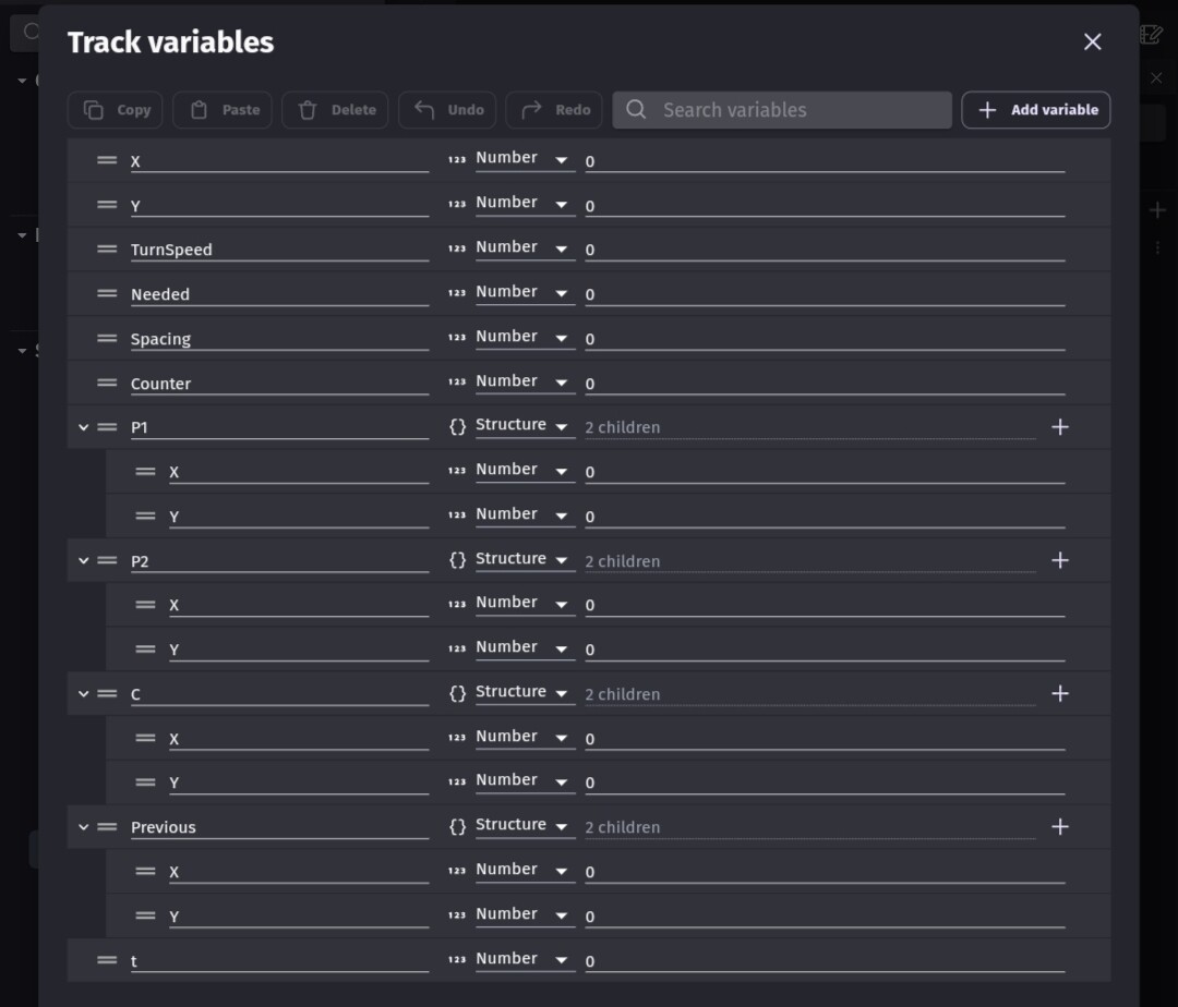
Variables. To make it easier to read, I used structures with X and Y for the points. The previous structure is used to track the last point so the arrows follow the curve. There might be a formula for this but this worked for me.

Scene

There’s a group that contains the points (start, end, control) This is just used for the is dragging condition so it doesn’t redraw the curve if an object isn’t being dragged. If the objects aren’t dragged like in my test project, then this wouldn’t be needed.
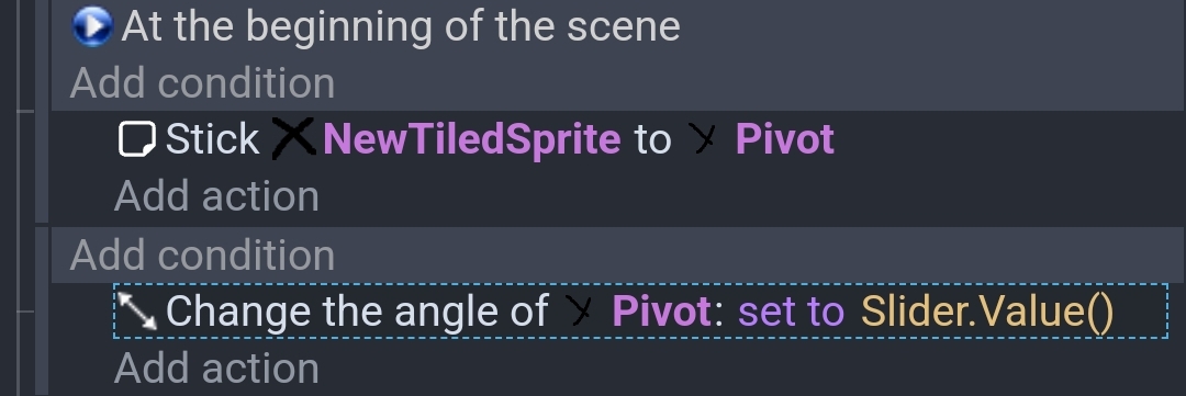
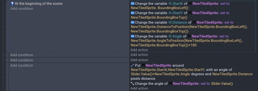
Events

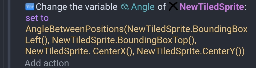
I would rather have added this project to my GitHub but I’m using the mobile version and this is in a testing project that has many different scenes. The formula will be the trickiest part to type. I would add the variables first.

Holy guacamole - you are a genius (as you added the curve to it too). I would’ve just been satisfied with a straight line (so now I am intrigued to replicate it in my game).

I asked the same question on learnmath reddit and got the equation from this tool.

Center Point X = Cx
Center Point Y = Cy
Angle = A
Length or Width of Line = L

Cx = x - L (cosA)
Cy = y - L (sinA)

This could be algebraically transformed to get to the x offset position as we know that the Cx is simply x + (L / 2).

I am also copying over the post from Chrispykins here - so we have all the possibilities (yours included in one place):

"The way to parameterize a circle which traces out a circle at a constant speed is to use sine and cosine. The point ( cos(t), sin(t) ) traces out a circle of radius 1 centered at the origin as ‘t’ increases (‘t’ is the angle). If you want to increase the radius of the circle by ‘r’, you just multiply by ‘r’ which looks like ( rcos(t), rsin(t) ). If you want to offset the center of the circle to some point (a, b), you just add that to the other point which looks like

( a + rcos(t), b + rsin(t) )"

You seem to have a better understanding of the equations. With help, I can implement most formulas. I have a basic understanding of sin() and cos(). I hope this helps. If not the formula, then at least the concepts of using an ID for each instance. I wish you luck.